Tag Archives: analog to digital

Quick Lesson in Non-Linearity

As its name implies, non-linearity is the difference between the graph of the input measurement versus actual voltage and the straight line of an “ideal” measurement. The non-linearity error is composed of two components, integral non-linearity (INL) and differential non linearity (DNL). Of the two, integral non-linearity is typically the specification of importance in most data acquisition (DAQ) systems.
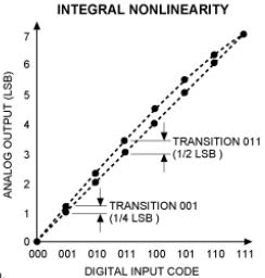
INL is the maximum deviation between the ideal output of a DAC and the actual output level (after offset and gain errors have been removed).

INL is the maximum deviation between the ideal output of a DAC and the actual output level (after offset and gain errors have been removed).

INL: The specification is commonly provided in “bits” and describes the maximum error contribution due to the deviation of the voltage versus reading curve from a straight line. Though a somewhat difficult concept to describe textually, INL is easily described graphically and is depicted in Figure 4. Depending on the type of A/D converter used, the INL specification can range from less than 1 LSB to many, or even tens, of LSBs.

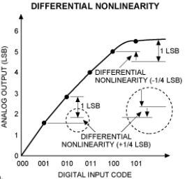
DNL: Differential non-linearity describes the “jitter” between the input voltage differential required for the A/D converter to increase (or decrease) by one bit. The output of an ideal A/D converter will increment (or decrement) one LSB each time the input voltage increases (or decreases) by an amount exactly equal to the system resolution.

DNL is the deviation between two analog values corresponding to adjacent input digital values.

DNL is the deviation between two analog values corresponding to adjacent input digital values.

For example, in a 24-bit system with a 10-volt input range, the resolution per bit is 0.596 microvolt. Real A/D converters, however, are not ideal and the voltage change required to increase or decrease the digital output varies. DNL is typically ±1 LSB or less. A DNL specification greater than ±1 LSB indicates it is possible for there to be “missing” codes. Though not as problematic as a non-monotonic D/A converter, A/D missing codes do compromise measurement accuracy.

Check out UEI’s Master Class Videos on Youtube.

Sample Rates: How fast is fast enough?

“How quickly must I sample my input signal?” It’s a fairly common question among DAQ system designers, and especially those without formal training in either DAQ systems or sample theory. The simple answer is the system must sample fast enough to “see” the required changes in input. In a purely input system, the minimum required sample rate is typically defined by Nyquist sampling theory. Harry Nyquist, pictured here, found that to recreate a waveform, you need to sample at least twice as fast as the highest frequency component contained in the waveform. Harry NyquistFor example, if your input signal contains frequency components up to 1 kHz, you will need to sample at 2 kHz, and more realistically, at 2.5 – 3 kHz. As with input resolution and accuracy, there is a tendency among DAQ system designers, particularly those new to the industry, to over-specify the system input sample rate. There are very few applications where it is necessary to sample a thermocouple more than 10 times a second, and most will probably be adequately served at a tenth that rate. Avoid the temptation to over-sample as it often increases system cost, memory requirements, and subsequent analysis costs without adding any useful information.

Note that the above pertains mostly to input-only systems. Control systems represent an entirely different set of considerations. Not only must the input sampling rate be high enough, but the CPU must have the horsepower to perform the calculations fast enough to keep the system stable and the output devices must have the speed and accuracy required to achieve the desired control results. A discussion of control theory is well beyond the scope of this blog, but here are a couple of thoughts that may be helpful.

First, if you need any sort of deterministic control, and/or a hiccup in your control algorithm would be problematic, or your system update rate is more than 10 updates per second, you will likely need to consider using a real-time or “pseudo real-time” operating system. To ensure 10 updates-per-second in most Windows/Vista environments, you should disable automated functions such as Windows Update or Automated backups. Many users also find that though it is not a fully deterministic real-time OS, Linux-based applications have low enough latencies to be used in some higher speed control applications. UEI offers technical support for QNX, RT Linux, RTAI Linux, RTX and XPC.

Grappling with Sampling?

Simultaneous sampling is somewhat of a misnomer. Samples can never truly be simultaneous as there’s always a certain skew between samples. However, sampling skews can generally be reduced to levels low enough that they are considered insignificant to the application. The error or skew between samples is commonly referred to as the aperture uncertainty, and is typically measured in nano-seconds (ns). As an example, the 4-channel, 250 kHz DNA-AI-205 offers a maximum aperture uncertainty of 30 ns.

There are two common ways to achieve simultaneous sampling. SimultaneousSampling1The first is to simply place a separate analog-to-digital (A/D) converter on each channel. They may all be triggered by the same signal and will thus sample the channels simultaneously.

The second is to place a device called a sample & hold (S&H) or track & hold (T&H) on each input. In “sample” mode, the device behaves like a simple unity gain amplifier. That is, whatever signal is provided on the input is also provided at the output. SimultaneousSampling2However, when commanded to “hold”, the S&H effectively freezes its output at that instant and maintains that output voltage until released back into sample mode. Once the inputs have been placed into hold mode, the multiplexed A/D system samples the desired channels. The signals it samples will all have been “held” at the same time and so the A/D readings will be of simultaneous samples. The second way to provide simultaneous sampling is to provide an independent A/D converter on each channel. Either system should provide good results.

Click here for more information about Sampling Rates: How Fast is Fast Enough?

UEIDAQ.com | Facebook | LinkedIn | Youtube | Twitter